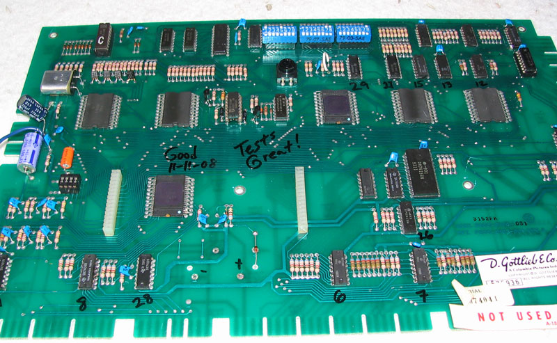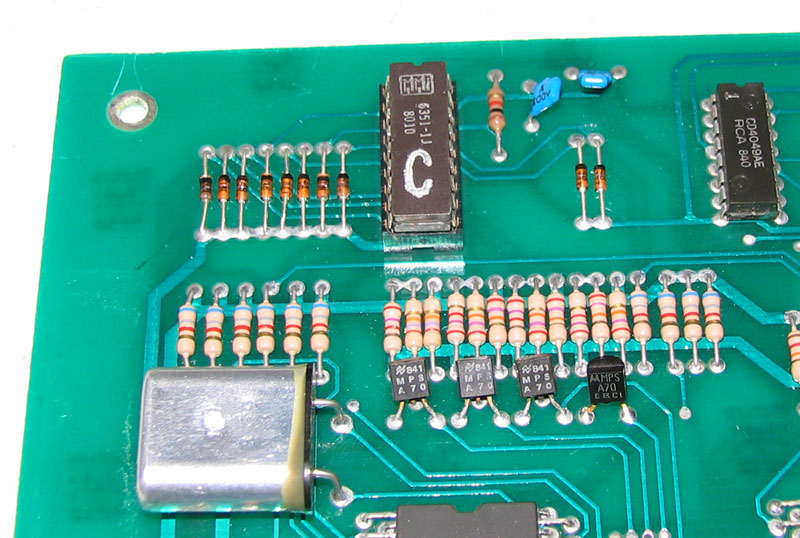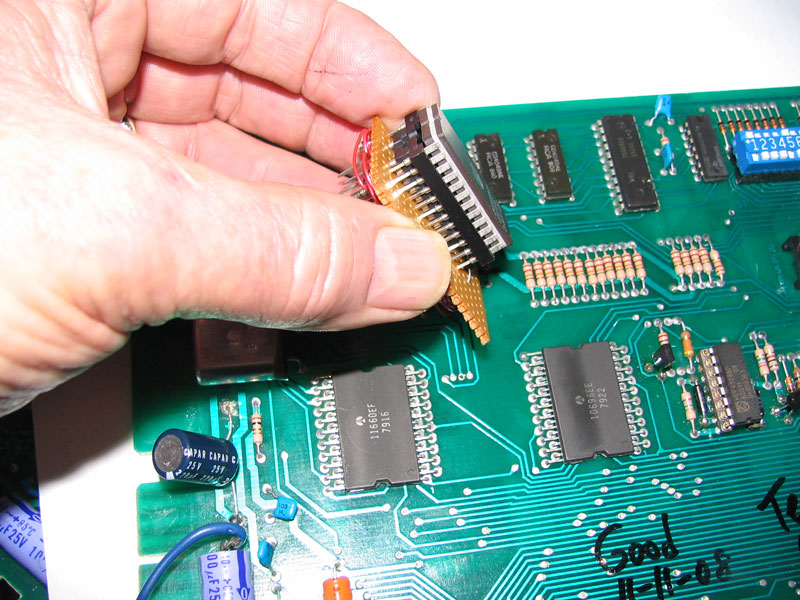
IntroductionDo you have an original Gottlieb System 1 CPU board that needs the PROM replaced or has a missing game PROM? Unless you can find another PROM for your game from a seller or collector, you can't buy and burn these old PROMs any longer. This is the problem I ran into when trying to fix a Close Encounters game that had an original CPU board I was able to repair, but the PROM was missing from the CPU circuit board. I've seen a replacement circuit board that can accept a newer 2716 EPROM which will fit into the 18 pin socket that was used for the original PROM, but I was unable to find one for sale. What to do? The answer is, make your own replacement board using off-the-shelf parts with some wire-wrapping skills. Once you build the PROM adapter, you can move it from one game to another if you need to. All you need is the ROM code for the original game, but that's in a 2716 EPROM format. Just burn the game's code in the 2716 and you are set to use the adapter with a working original CPU board. Why do you need to build a piggy-backed setup as I describe below? Because the chip sizes are different due to addressable space in the 2716 EPROM. You will be trying to make a 20 pin chip plug in to an 18 pin socket and obviously that will require a modification. You can do this by piggy-backing a 20 pin socket which will accept your 2716 EPROM on top of an 18 pin socket which will plug in to your games existing 18 pin socket. The pins from the 20 pin socket don't actually plug in to the 18 pin socket, but will be available for wire-wrapping between the legs of the two sockets using the technique I show below. Gottlieb System 1 PROM LocationThe pictures below show a Gottlieb System 1 CPU board, and the location of the original PROM.
Adapter Parts RequiredThe "adapter" which adapts a newer 2716 PROM to be used in place of the original 18 pin PROM requires few parts. Here's what you need:
As you can see, there isn't much required to do this job in the way of parts. If you can't find an 18 pin wire wrap socket, you may be able to find a 20 pin wire wrap socket and remove the extra two legs on one end since they won't be used. You may also choose to buy a wire wrap pin strip that could be used instead of the 18 pin socket. In my case, I had some 18 pin wire wrap sockets so I simply used one to build my first adapter. The key item that you may not have is the EPROM burner. You can find someone to burn the EPROM for you if you don't want to invest in a burner ( EPROM programmer). Wire Wrap Pin ConnectionsFor this to work, you need the wiring list so you can wire wrap one pin to another. Here are the connections:
Notes
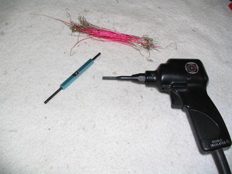
Wire Wrap ToolsThe pictures below show the wire wrap tools used for the adapter. I use a wire wrap gun that is electric to wrap the wires, and I use the blue tool for unwrapping a wire wrap that may have been done by mistake. The blue wire wrap tool was purchased from Radio Shack many years ago and is still used when I want to do manual wire-wrapping as opposed to using the more professional electric wire wrap gun. The center of the blue tool contains a wire stripper so that you can slide the end of the insulated wire through the tool and then pull it to remove the insulation. I don't use this tool for stripping wire since I like my fancy wire stripper, but I have used it in the past and it works OK.
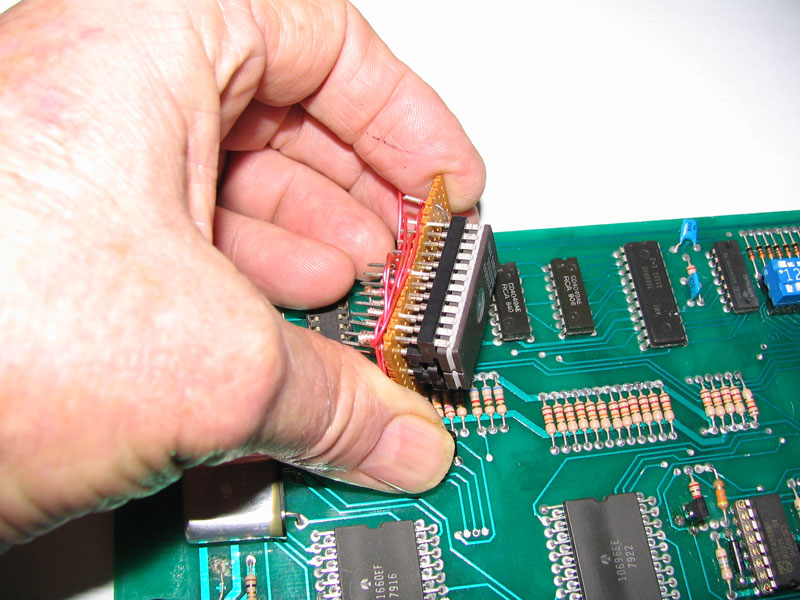
Wire Wrapping The SocketsWith the parts in hand, the wire wrap chart, and the wire wrapping tools shown above, it's now time to begin the wire wrapping process. Here is the process I followed: - First, I pushed the 18 pin wire wrap socket through the perf board. - Then I piggy-backed the 24 pin wire wrap socket above it and pushed it through the perf board too. - Once through with this, I used a box cutter to score the perf board to a smaller size rather than retaining the larger perf board I started with. - After scoring a few times, I bent the perf board back and forth until the perf board broke along the score line. - Then it was time to start wrapping some wires between pins. I began by keeping the sockets pushed tight against the perf board and wrapped pin 1 of the 18 pin socket to pin 24 of the 24 pin socket. - Then I wrapped pin 9 of the 18 pin socket to pin 12 of the 24 pin socket. This is the Ground pin for both sockets. - Then I wrapped pin 12 of the 24 pin socket to pin 18 of the 24 pin socket to ensure I didn't forget about connecting the Ground pins between both sockets. - I wrapped pin 18 of the 24 pin socket to pin 19 of the 24 pin socket. Note that this means there are two wires wire-wrapped on pin 18 since the other wire goes to pin 12 of the 24 pin socket. - I also connected pin 20 to the 18 pin socket pin #14 (ground). Pin 20 also has two wires connected to it. - I used needle nose pliers to wrap one end of the .1 microfarad cap to pin 12 of the 24 pin connector, and the other end of the capacitor to pin 21 of the 24 pin connector. Note that pins 12 and 21 also have two wires connected to them. Why is this important? Because the pins that have two wires connected to them will affect the length of the 20 pin socket pins when you cut them shorter. You won't want to wrap as many turns of wire on these pins in order to keep the pin length short when you cut the 20 pin socket pins to a shorter length. - At this point I had the sockets tight against the perf board and held in place with enough wires that I could cut the 24 pin socket pins down to a smaller size so they wouldn't interfere with the adapter when it was plugged into the CPU board's 18 pin socket. - I pretty much followed the left side of the wiring chart above and then moved over to the right side of the chart ensuring wires were connected correctly between the sockets. In some cases, the wiring on the 24 pin socket goes from one pin to another pin on the same 24 pin socket. Programming The 2716 EPROMI program (burn) enough EPROMs (due to my large collection of games) such that it warrants owning an EPROM programmer. In my case, I use a True-USB Willem Programmer (GQ-3X model) found at www.mcumall.com. I tried several of their programmers before I settled on this one. It seems to burn most every kind of EPROM found in pinball games so it works OK for me. It doesn't have an enclosure and the board is exposed, but that's good enough for what I'm doing. I have an older Needham EMP-10 programmer that I used for years, but it requires a slower speed computer and a parallel port which is harder to find on new computers. I think the limit for the EMP-10 is a computer CPU speed of around 600 Mhz. I don't know about you, but my computers are all high end, highest speed computers that can be bought, so it was time for the EMP-10 to be replaced. If you don't have a programmer, then try John since he provides an EPROM programming service to many pinheads. You will also need the ROM code for the game you are interested in, and it needs to be in the 2716 format. Click HERE to download all of the Gottlieb System 1 ROM files found in the single zip file. Find the name of your game and extract it from the zip file so that it can be read into the programmer. Once loaded, and assuming you have a blank 2716 EPROM with the correct programmer settings for burning a 2716, just write the file to the EPROM and your burner will take over and burn a new EPROM that can be plugged into the adapter's 24 pin socket. Adapter PicturesBy now you should have correctly wrapped wires between the various socket pins on both the 18 pin socket and the 20 pin socket. You won't be able to follow all of my wire wrap work by viewing the photos, but you can get an idea of what the adapter looks like after wire wrapping the socket pins and viewing the pictures below. I would suggest testing the adapter in a System 1 game after you burn the 2716 EPROM and ensure it works correctly. If it doesn't, and you know the CPU board is good, and you burned the correct game ROM code, then remove the adapter and check your wiring against the wire chart above. Total time to build the first adapter was about one hour. I built a few more and they took about 30 minutes each since I was obviously getting more efficient due to familiarity with the required work. At first I thought I was just lucky, but mine came out fine the first time I did it. I tried the adapter in several System 1 games using an EPROM burned for each game and it worked fine. The other adapters turned out fine too so I guess luck may not have been in play for this job.
Hopefully you have found this informative and worded in such a way that the directions are clear. Now you don't have to worry about chasing down an old PROM for your System 1 game. Just build your own adapter. Good luck!
|