|
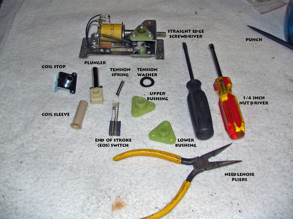
This page shows pictures with short descriptions for how to rebuild a Gottlieb System 1 flipper mechanism. Tools Tools to do the rebuild are somewhat simple. You need the following:
Flipper Rebuild Parts If you buy the parts from The Pinball Resource, you will find the following new parts in the kit:
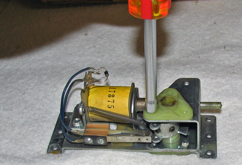
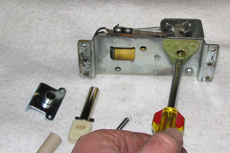
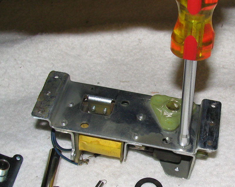
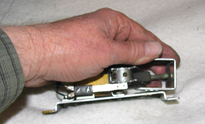
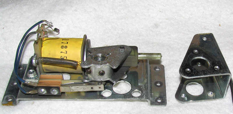
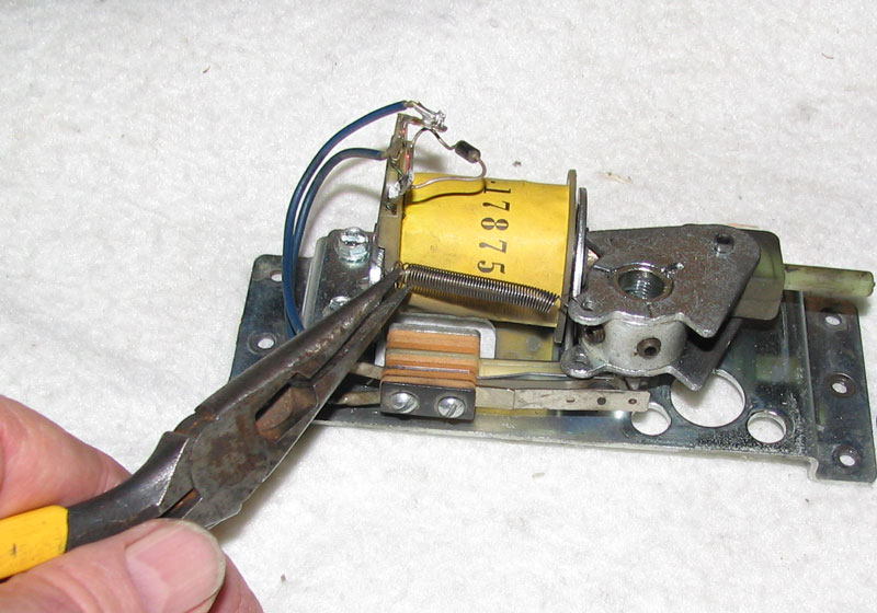
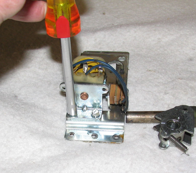
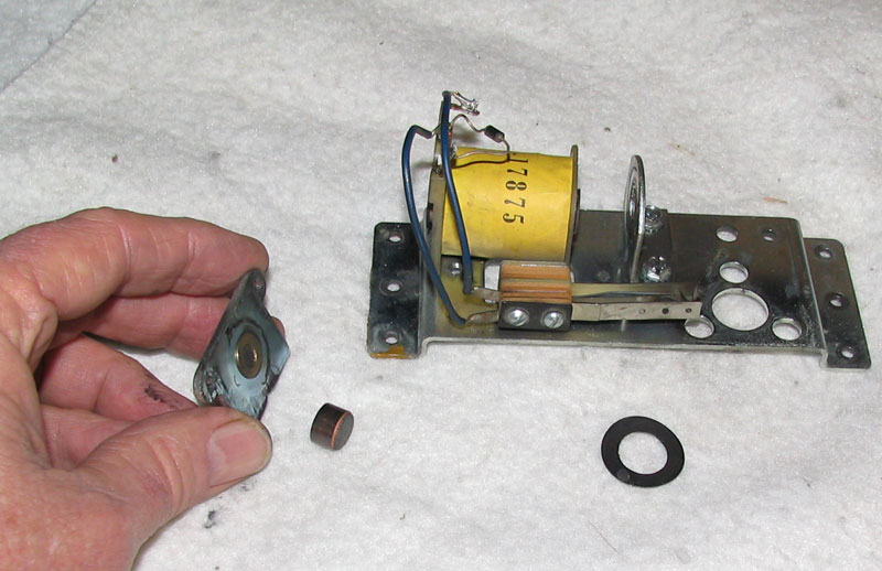
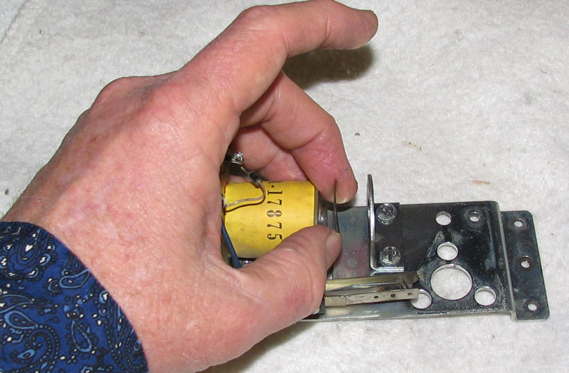
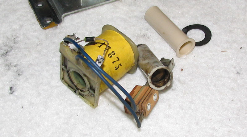
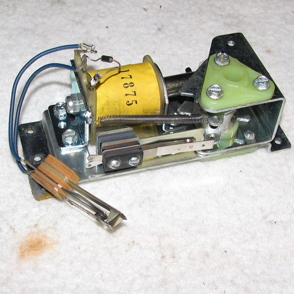
The area where you can make a mistake is mostly around the plastic flipper shaft bushings. One of the bushings has a raised area (crudely shown and labeled in the picture) where the screw holes are located. This bushing goes on the bottom side of the bushing bracket, NOT the top. The raised area rests in the holes of the bushing bracket on the underside of the flipper assembly. You'll find out if you made a mistake when you try to screw the bottom bushing in to the top of the bushing bracket. It won't work correctly. One other thing you can do wrong is position the plunger facing the wrong direction in the pawl. It makes a difference, so pay attention to how the plunger is held in place with the pivot pin and duplicate the new plunger's position when you replace it. I use a socket (about 3/4 inch works fine) and position the pawl with the old plunger held in place with my fingers and with the pivot pin over the socket, and then use the punch to drive the pin towards the inside of the socket. The socket is used to keep the pawl above a surface since that's the only way the pivot pin can be driven out. Once the pin is driven out, you won't need the socket anymore. Just put the new plunger in place in the correct direction and place the pivot pin on either side of the pawl and drive it in with your hammer. Watch out for your fingers when hammering the pivot pin since the pin isn't that long. You don't need the punch to drive the pin in to the pawl and through the plunger, just use your hammer and hammer the pin directly. I drive the pin in far enough that an equal amount of the pivot pin is showing on both sides of the pawl. Note that when removing the pin, you'll probably be hitting your punch rather hard with the hammer. The pin is a tight fit in the pawl. Don't forget the coil tension washer since this dampens coil movement and takes up any slack that would be present between the coil and the coil stop. It is placed between the end of the coil and the coil sleeve bracket closest to the pawl. You'll notice that the tension washer is somewhat concave. I've seen these mounted in games either facing the coil or away from the coil. I put it in place with the concave side towards the flipper pawl. Finally, after putting everything back together, I replace the End of Stroke (EOS) switch but I leave the wires still connected to the old EOS switch. Then when soldering the flipper coil wires on to the flipper lugs, I also heat up the wires soldered in the old EOS switch and remove them from the switch. Then I move the wires over to the new switch. It doesn't matter which wire goes on a particular EOS lug. You can solder either wire on either EOS lug since this is a simple switch that only opens and closes. I do this at the same time when I solder the coil wires because I like to solder everything at once, rather than doing it two different times. Pictures (click any picture to enlarge)
|