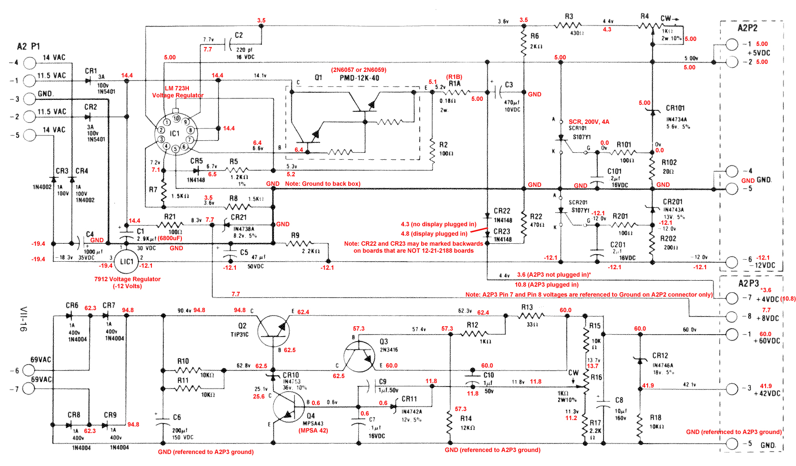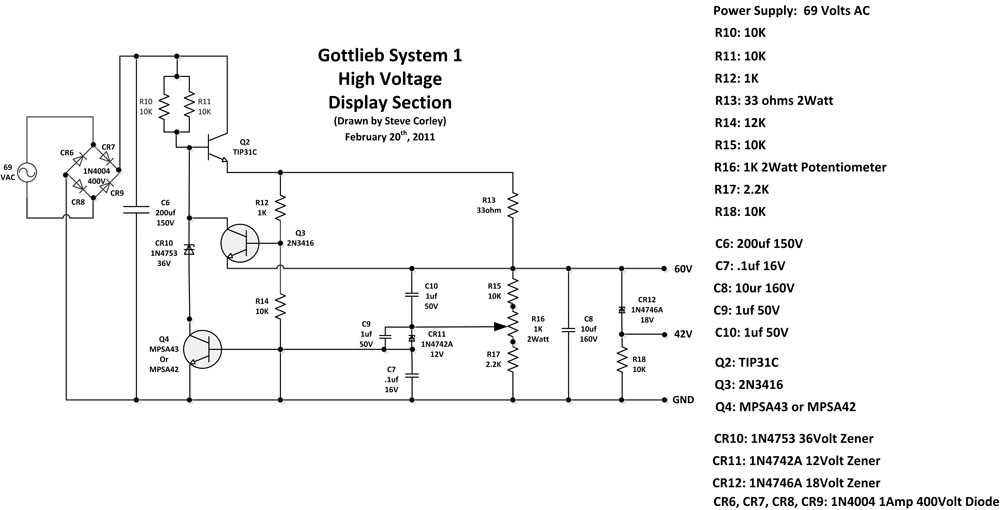
IntroductionThis page was created as a place for me to quickly access the schematic for a Gottlieb System 1 Power Supply. I love System 1 games, and although you can buy a Great Plains Electronics or a Rottendog power supply to replace the original Gottlieb power supply, I have found that the power supply that came with the game can often be updated or repaired if faulty. Since I get questions about this power supply from other System 1 fans, I decided to create this page showing the schematic with various voltages and other info that I find myself often repeating. I also created a separate schematic for the high voltage display section of the original power supply that is easier to read than the original schematic. I decided to use a good working and restored original power supply to measure voltages and note them on the schematic. I discovered a couple of things in the process of doing this such as some original boards may have CR22 and CR23 mislabeled on the circuit board, but I also found that the voltages can be somewhat different than what is shown on the original schematic for the game. This isn't that unusual since there are many components on the circuit board that can yield different measurements, but I thought I would go ahead and measure the voltages anyway and use an image editor to show the info on the schematic in case others (as well as me) might find it helpful. I also discovered that the voltages that affect the displays can be different depending on which ground you use as well as whether the A2P3 connector is plugged in or not. The voltages that are shown on the schematic assume you do NOT have connectors plugged in except for the AC input voltage that is found on A2P1. This is the connector at the bottom of the power supply as you view the power supply installed. So, the schematic can be a little misleading if you assume the voltage measurements are what you too should find. When measuring the voltages on A2P2 (the upper connector on the power supply), you can attach your meter's ground lead to the negative side of C1. This is the large capacitor that is just above the A2P1 connector. You can also use pin 4 or pin 5 on A2P2 as your ground connection for your meter. Original power supplys used a 2900uF electrolytic capacitor for C1. I've had good luck replacing mine with a 4700uF or 6800uF capacitor. This is a filter capacitor for the 5 volt and -12 volt portion of the circuit, and using a 4700uF capacitor, I don't see much in the way of ripple even when all of the connectors are plugged in. The point is that the original 2900uF capacitor will work for C1, but it's a little on the wimpy side and should be replaced not only because it is wimpy, but because as an electrolytic capacitor it's probably dried out anyway and not functioning as well as it did when it was new. A 4700uF capacitor will work just fine and a 6800uF capacitor works a little better. Note that if you decide to use a Ni-wumpf replacement CPU board you will find that it doesn't use the -12 volt supply, so -12 volts isn't needed. When you measure the A2P3 voltages (this is the bottom right connector on the power supply) there are a couple of things to note. First of all, you use the ground that's found on pin 5 of the A2P3 connector when measuring voltages, not the ground that's found on the L-frame (this is the L shaped piece of metal the circuit board is mounted to), C1's negative side of the capacitor, or pin 4 or pin 5 on A2P2. A2P3 uses a different ground than the rest of the circuit which pertains to the 5 volt and -12 volt supply. The A2P3 connector uses an AC input from the smaller 69 VAC transformer that's found in the bottom of the cabinet next to the larger transformer which supplies 11.5 VAC and 14 VAC. Another thing to note when measuring the voltages on A2P3 is in regards to measuring the 4 VDC on pin 7 and 8 VDC on pin 8. You use the ground from A2P2 (or the negative side of C1) to measure these voltages. If you reference pin 7 and pin 8 to the ground on pin 5 of A2P3 you will see around 0 volts rather than the 4 volts and 8 volts you might expect to see. This is because the 4 volts and 8 volts are supplied by the same part of the circuitry used to supply the 5 volts and -12 volts, NOT the part of the circuitry that supplies the 60 VDC and 42 VDC voltages. It also makes a difference whether you have the connector plugged in to A2P3. If you have the connector plugged in (this connector affects the displays), pin 7 will not read 4 volts as you might expect, but more like 10.8 volts. So when viewing the schematic, note that it assumes only the A2P1 connector is connected when measuring voltages. My schematic notations show the voltages I found when all of the connectors are connected. I added some extra notes on the schematic as well regarding a couple of the parts such as the LM 723 voltage regulator can and the Q1 replacement power transistor. I also show the voltages for pins 7 and 8 on A2P3 with the connector plugged in, and with it off. When the connector isn't plugged in to A2P3, I found 3.6 volts for pin 7 (rather than the expected 4 volts). With the connector plugged in to A2P3, the voltage on pin 7 was 10.8 volts. Gottlieb System 1 Power Supply Schematic With VoltagesThe first picture below is the System 1 power supply with voltage notations plus other info. You can click on the image to see the full-size view of the schematic which can be saved or printed. I also include a pdf of the schematic. The second picture is the System 1 high voltage display schematic that has been rearranged by me so that it is easier to read. I also include a list of the various parts used in the high voltage section. (click picture to enlarge)
Hopefully you find these schematics of value. Good luck!
|